Showing posts with label automobile. Show all posts


Slipper Clutch – How Does it Work?

The actual difference between the slipper clutch and normal clutch is the clutch hub. The base of clutch is on the right side and the hub of clutch is on the left side. You can see ball and ramp in the clutch base and ramp and engagement dogs in clutch hub (It may come with or without ball bearings, this one is without ball bearing). In normal operation, when the engine is trying to turn the rear wheel, the flat engagement dogs push on each other, and the clutch drives the motorcycle forward like a normal clutch operation.

During massive deceleration or hard breaking the torque forces the ramps together. To absorb engine braking force the ramps slide up on each other. This action lifts the hub up from the base, in the direction of pressure plate. It slides until the entire braking force is absorbed and then act like a normal clutch. This mechanism is called “spring loaded ball sliding up ramp”. The above process absorbs the engine braking force and partially disengages the clutch from the engine.


When you are riding at high speeds and suddenly you encounter a sharp corner – the obvious reaction would be to slow down by applying the brakes and shifting in lower gear. But what if you have lesser time and you want to shift 2-3 gears at a time? And when you do this, you do it at the cost of damaging the gear box and putting your safety at risk which arises due to engine braking force. As a mechanism to reduce these issues, Slipper Clutch (also known as back torque limiter clutch) was introduced. Slipper Clutch helps by allowing the clutch to partially slip until the engine speed matches your own speed.

In normal clutches, the engine braking force is transmitted to rear wheel via chain drive (or shaft drive) which causes rear wheel to shake, jump or lose traction. This is the main concept behind slipper clutch – to control rear wheel under hard braking and downshifting that causes the rear wheel to lose traction. It is particularly helpful especially on higher displacement bikes where the engine braking force is massive and may cause the motorcycle to go out of control, resulting in a high-speed collision/accident!

Clutch Stake height:

Clutch stack height is more critical in a slipper clutch than in a normal clutch. The slipper clutch tends to work the best with a clutch stack height that is about 1 mm more than the distance between the clutch hub base and the pressure plate.

Clutch Plate:

Clutch plate order for slipper clutches may vary from the original method due to the clutch hub lifting off of the base. Some clutch plates include special friction plate and judder spring apart from steel plate and friction plate to engage the clutch smoother. In such conditions the first plate which is closest to the engine should be a friction plate. The second plate is a steel plate after, followed by special friction and judder spring.

Slipper Clutch Advantages

The following are the advantages of slipper clutch over normal clutch…

  1. Slipper clutch reduces sudden forces on the inside of the transmission and hence, reduces wear and tear on the transmission
  2. Correctly installed slipper clutch improves performance.
  3. It can prevent disastrous rear wheel lock up in case of engine seizure or transmission failure.
  4. It also reduces work of suspension by absorbing engine braking force hence less bumpy ride while cornering.
  5. The rider does not need to concentrate on clutch operation which allows him to concentrate on other things such as body posture, braking etc while cornering.

Slipper Clutch Disadvantages

Practically there are no disadvantages of slipper clutch but hypothetically there are a few, such as…

  • It’s mechanically complex. Some slipper clutches are really complex to install and deal with (not many of them).
  • They are expensive (not against the saving they make by reducing wear and tear of transmission, less suspension movement and increased rider safety).
  • Sometimes you really need the engine braking force to slow down the bike (but how many times?) which can work against the concept and investment on slipper clutch.
  • Slipper clutch can’t give desired results if not adjusted according to requirements.


One of the most important control system of an automobile is BRAKE SYSTEM .They are required to stop the vehicle within the smallest possible distance and is done by converting kinetic energy of the vehicle into heat energy which is dissipated into atmosphere.
The main requirements of brakes are given below:-
  1. The brakes must be strong enough to stop the vehicle within the minimum possible distance in an emergency. But this should also be consistent with safety. The driver must have a proper control over the vehicle during emergency braking and the vehicle must not skid.
  2. The brakes must have good antifade characteristics and their effectiveness should not decrease with constant prolonged application.

The actual stopping distance of vehicle while braking depends on the following factors:-
1. Vehicle speed
2. Condition of the road surface
3. Condition of tyre tread
4. Coefficient of friction between the tyre tread and the road surface
5. Coefficient of friction between the brake drum/disc and brake lining/friction pad
6. Braking force applied by the driver

TYPES OF BRAKES


The brakes for automotive use may be classified according to the following consideration
1. Purpose
a). Service or primary brakes
b). Parking or secondary brakes
2. Construction
a). Drum brakes
b). Disc brakes
3. Method of Actuation
a). Mechanical Brakes
b). Hydraulic Brakes
c). Electric Brakes
d). Vacuum Brakes
e). Air Brakes

DISC BRAKES

Disc brake consists of a cast iron disc bolted to the wheel hub and a stationary housing called caliper. The caliper is connected to some stationary part of the vehicle, like the axle casing or the stub axle and is cast in two parts, each part containing a piston. In between each piston and disc there is a friction pad held in position by retaining pins, spring plates etc., passages are drilled in the caliper for the fluid to enter or leave each housing. These passages are also connected to another one for bleeding.
When the brakes are applied hydraulically actuated pistons move the friction pads into contact with the disc, applying equal and opposite forces the later. On releasing the brakes the rubber sealing rings act as return springs and retract the pistons and the friction pads away from the disc.

CONSTRUCTIONAL FEATURES

Two types of brake discs are generally used the solid type and the ventilated type. The ventilated type is more efficient since it provides better cooling. But they are thicker and heavier than solid type, they are liable to wrap at severe braking conditions, the dirt accumulates in the vents which affects cooling and apart produces wheel imbalance.
The discs of the brakes are made of pearlite gray cast iron. The material is cheap and has good antiwear properties. Cast steel discs have also been employed in certain cases, which wear still less and provide higher coefficient of friction. Their main drawback is the non uniform frictional behavior.
The other materials used for the manufacture of disc are
1. Aluminium
2. CeramicObviously, cast-iron disc is the heaviest part of a brake - about 8 kg each, or 32 kg per car. Aluminium alloy discs are used in the Lotus Elise. Though light, they were less resistant to heat and fade, thus more powerful Elises still employ conventional cast-iron disc. 
In contrast, carbon-fiber disc is most heat-resisting yet is by far the lightest, however, it requires very high working temperature, and otherwise braking power and response will be unacceptable.
Ceramics are inorganic, non-metallic materials that are processed and used at high temperatures. They are generally hard brittle materials that withstand compression very well but do not hold up well under tension compared to the metals. They are abrasive-resistant, heat resistant (refractory) and can sustain large compressive loads even at high temperatures. The nature of the chemical bond in the ceramics is generally ionic in character, and the anions play an important role in determination of the properties of the material. Typical anions present are carbides, borides, nitrides and oxides. The different types of ceramics are clays, refractories, glasses etc.
Cast iron has been the material of choice for brakes rotors since the introduction of disc brakes during the 50?s.Elise made a new era, being the first road production road car to use aluminium metal matrix composite discs inserted on four wheels. Aluminium is better rotor material than cast iron due to two main reasons: its density is as one third as cast iron but its thermal conductivity is three times greater. These factors made it possible to construct a much lighter brake disc.

Even though there are many different suspension setups, most types can be categorized into one of these types: MacPherson strut, modified strut, multilink, short/long arm, I-beam, and solid axles. Regardless of the type, all suspensions try to accomplish the same goals of good ride quality and handling.

Macpherson Struts
The popularity of small FWD vehicles has brought with it the dominate type of suspension system used today, the MacPherson strut suspension. These systems combine a coil spring, shock absorber, and bearing plate into a single unit. A typical strut is shown in Figure 6-32.
This arrangement allows for greater engine compartment space and reduced weight compared to short/long arm suspensions. This is because the MacPherson strut suspension eliminates the upper control arm and upper ball joint. This reduces weight and moves the top of the suspension higher and toward the outside of the vehicle. Because the upper control arms are removed, there is space for the engine and transmission to be mounted transversely (sideways) in the engine compartment.
The strut connects to the car body through the upper strut mount or bearing plate, which also acts as a pivot and damper. The upper mount provides flexibility, so the strut can change angle to follow the path of the lower ball joint. The mount also dampens or reduces vibration and serves as the upper pivot for the steering axis. The components of a strut mount are illustrated in Figure 6-33.
 The shock absorbers piston rod in a strut is larger than the standard shock piston rod to withstand sideways bending from loads placed on the tire while it is turning. Figure 6-34 shows a comparison of a strut piston and a shock piston. The strut piston rod, on the left, is much larger in diameter than that of the shock, shown on the right.
Modified Struts
Some vehicles use a strut-style shock absorber but relocate the spring. These are not true MacPherson struts. Called a modified strut, this system has the spring mounted separate from the strut. The strut performs the function of the shock absorber and is connected to an upper bearing plate at the top and to the steering knuckle at the lower end. The coil spring is located between the frame and the lower control arm. This design has the weight and space saving advantages of the MacPherson strut suspension but can contain larger springs. Relocating the spring also can allow for a wider distance between the wheel wells, increasing engine compartment room.
Multilink
Many vehicles use a multilink system. With a multilink suspension, the steering knuckle is taller than on a traditional strut or short/long arm suspension, often reaching the height of the top of the tire. The strut does not turn with the steering axis; rather it is mounted rigidly to the body at the upper strut mount. This is because the steering knuckle pivots on the upper and lower ball joints for steering action. Multilink systems are designed to produce neutral steering on FWD vehicles, which tend to exhibit understeer with traditional MacPherson strut suspensions. This suspension is also commonly used on RWD cars, light trucks, and SUVs.
 Figure 6-36 shows a common multilink arrangement. Multilink suspensions are also found on the rear of many vehicles, both FWD and RWD. Several control arms are used to reduce rear axle movements and provide better handling and ride qualities than a traditional rear strut system.

Short/Long Arm
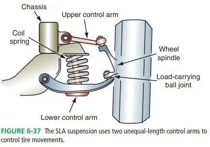
Short/long arm suspensions, also called SLA suspensions, are typically used on RWD vehicles. This suspension consists of two unequal length control arms connected with a steering knuckle. The control arms are generally triangular and are often called wishbones or A-arms. A steering knuckle, control arm bushings and ball joints comprise the rest of the suspension.

Figure 6-37 shows an illustration of a typical system. Control arm design is matched with the spring for tire control and ride characteristics. The control arms are mounted to the frame with control arm bushings. Some suspensions use a lower control arm with a single frame mounting point. In this case, a strut rod will also be used as an additional mount and stabilizer for the control arm as shown in Figure 6-38.
 SLA systems use two ball joints, one of which carries the sprung weight of the vehicle. The other ball joint provides a friction and pivot point and does not carry weight. The load-carrying joint is located in the control arm in which the spring sits. The other ball joint is called the friction or following ball joint.

 Figure 6-39 shows how the weight is carried by the load-carrying ball joint in an SLA suspension. SLA suspensions are not as common as they once were due to the popularity of FWD vehicles. These suspensions tend to intrude into the engine compartment, causing space problems with FWD drivetrains.
I-BEAM
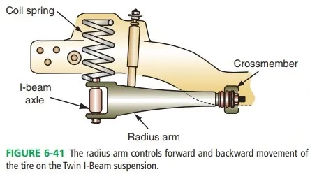
This suspension system was used on Ford trucks and vans for many years. Twin I-beams are strong and simple like solid axles but provide independent movement of the front suspension. An illustration of this system is shown in Figure 6-40. I-beams are mounted to the crossmember with a bushing and house the ball joints at the outside of the beam. I-beams also use a radius arm to control I-beam movement, as shown in Figure 6-41. I-beams are similar to very long control arms. They move on a pivot and allow for vertical wheel movement while the radius arm stops forward and backward movement of the suspension.


1. Chain Drive


This is the drive system that an overwhelming majority of motorcycles implement. The sprocket connected to the gearbox output shaft is the driving sprocket and the one at the rear wheel is the driven sprocket, both are connected through a chain, which also comes in a variety of designs, but we’ll leave that discussion to some other day.
Now a chain drive system requires you to tighten it from time to time as the chain has a tendency to increase in length with time. There is an in-built provision in the swing-arm in motorcycles with chain drive systems to allow the rear wheel to move backwards by a limited extent. One has to check the motorcycle every 500-700 km for slack and adjust it if required. In addition, since chain drive systems are generally open to the elements and catch a lot of dust and grime, they have to be cleaned and lubricated every 500-700 km. This makes chain drive systems pretty service intensive and bothersome to an extent. Chain drive systems are also quite noisy, especially when the chain loosens. In addition to the regular maintenance they require, chain drive systems also need to be replaced every 15,000 to 25,000 km, depending on factors such as power output of the motorcycle, usage patterns and maintenance levels.

2. Belt Drive


A belt drive system isn’t as common as a chain drive system, though in terms of popularity, it stands at a distant second position. This setup comprises of a driving pulley towards the gearbox output shaft and a driven pulley at the wheel – the two pulleys are connected by a belt which has teeth, or grooves on the inner side, matching the grooves on the outer side of the pulleys.  The belt is made of a rubber-like, but mostly a very strong synthetic material which lasts a very long time. Modern drive belts are strengthened with steel wires inside and Kevlar coating outside – such belt systems can last really long. You can expect a well maintained belt drive on a motorcycle to last in excess of 100,000 km or even more. Unlike chain drive, which requires very frequent cleaning, tightening and maintenance, belt drives are relative maintenance free.
Seems too good to be true, doesn’t it? So if a belt drive system offers so many advantages, then why aren’t they used more commonly? Well, as the case with every good thing in the world, they have their own downsides too. Belt drive systems are essentially costlier to produce than a chain-sprocket system. Secondly, the power loss during the transmission, depending on how the system has been set-up, ranges anywhere from 9 to 15 percent, which is quite high compared to a chain drive system. Also, while a belt drive system does not require regular maintenance, if ever the belt or any other components of the system give way, they are much more expensive to replace than the chain and sprocket setup.
Belt drives are generally used in cruisers where they offer noise-free, smooth transmission for long distance riding. Since comfort and smoothness is more important here as compared to performance or fuel efficiency, the belt drive system lends itself well to the application.

3. Shaft Drive


shaft drive systems are the most expensive of the three systems we have here, and by some margin. They are, however, the sturdiest of the three, very smooth, and hardly ever need any maintenance. If designed and engineered well, drive shafts often last the life of a motorcycle without requiring any servicing or maintenance whatsoever. This system, as the name suggests, comprises of a shaft that’s connected to the gearbox output via a universal joint, which is essentially a coupling that facilitates transmission of rotary power at any selected angle. At the other end, the shaft is connected to the rear wheel hub via a spiral bevel gear. The bevel gear turns the direction of rotation of the shaft by 90 degrees to make the wheel turn. This entire drive system is bathed in oil for lubrication and sealed to protect it from any external elements, which makes it totally maintenance free.
Since shaft drive systems are heavy, expensive, and by themselves require more torque to work efficiently, they are not used on low-capacity or economy oriented motorcycles. They are used on large capacity (generally 600cc or above) motorcycles which produce good amounts of torque. Also, since shaft drive systems are very sturdy and reliable, they are often used in motorcycles built for the purpose of adventure, sports touring or adventure touring.These systems lose a lot of power during transmission. They are the most inefficient of the trio we have here and may bleed from 20 to 25% of the power by the time they transfer it to the rear wheel.


It is very interesting to know about complete combustion in automobile engineering, because in actual practice, perfect combustion is not at all possible due to various losses in the combustion chamber as well as design of the internal combustion engine. Moreover the process of burning of the fuel is also not instantaneous. However an alternate solution to it is by making the combustion of fuel as fast as possible. This can be done by using two spark plugs which spark alternatively at a certain time interval so as increase the diameter of the flame & burn the fuel instantaneously. This system is called DTSI (Digital Twin Spark Ignition system). In this system, due to twin sparks, combustion will be complete.

This article represents the working of digital twin spark ignition system, how twin sparks are produced at 20,000 Volts, their timings, efficiency, advantages & disadvantages, diameter of the flame, how complete combustion is possible & how to decrease smoke & exhausts from the exhaust pipe of the bike using Twin Spark System.

How Does It Works?
Digital Twin Spark ignition engine has two Spark plugs located at opposite ends of the combustion chamber and hence fast and efficient combustion is obtained. The benefits of this efficient combustion process can be felt in terms of better fuel efficiency and lower emissions. The ignition system on the Twin spark is a digital system with static spark advance and no moving parts subject to wear. It is mapped by the integrated digital electronic control box which also handles fuel injection and valve timing. It features two plugs per cylinder.
This innovative solution, also entailing a special configuration of the hemispherical combustion chambers and piston heads, ensures a fast, wide flame front when the air-fuel mixture is ignited, and therefore less ignition advance, enabling, moreover, relatively lean mixtures to be used. This technology provides a combination of the light weight and twice the power offered by two-stroke engines with a significant power boost, i.e. a considerable "power-to-weight ratio" compared to quite a few four-stroke engines.

Moreover, such a system can adjust idling speed & even cuts off fuel feed when the accelerator pedal is released, and meters the enrichment of the air-fuel mixture for cold starting and accelerating purposes; if necessary, it also prevents the upper rev limit from being exceeded. At low revs, the overboost is mostly used when overtaking, and this is why it cuts out automatically. At higher speeds the over boost will enhance full power delivery and will stay on as long as the driver exercises maximum pressure on the accelerator.

Main characteristics
• Digital electronic ignition with two plugs per cylinder and two ignition distributors.
• Twin overhead cams with camshaft timing variation.
• Injection fuel feed with integrated electronic twin spark ignition.
• A high specific power.
• Compact design and Superior balance. 

Construction
Digital twin spark ignition technology powered engine has two spark plugs. It is located at opposite sides of combustion chamber. This DTS-I technology will have greater combustion rate because of twin spark plug located around it. The engine combust fuel at double rate than normal. This enhances both engine life and fuel efficiency. It is mapped by the digital electronic control box which also handles fuel ignition and valve timing.
A microprocessor continuously senses speed and load of the engine and respond by altering the ignition timing thereby optimizing power and fuel economy.

Advantages
• Less vibrations and noise
• Long life of the engine parts such as piston rings and valve stem.
• Decrease in the specific fuel consumption
• No over heating
• Increase the Thermal Efficiency of the Engine & even bear high loads on it.
• Better starting of engine even in winter season & cold climatic conditions or at very low temperatures because of increased Compression ratio.
• Because of twin Sparks the diameter of the flame increases rapidly that would result in instantaneous burning of fuels. Thus force exerted on the piston would increase leading to better work output.

Disadvantages
• There is high NOx emission
• If one spark plug get damaged then we have to replace both
• The cost is relatively more


Powered by Blogger.