Showing posts with label Brakes. Show all posts


One of the most important control system of an automobile is BRAKE SYSTEM .They are required to stop the vehicle within the smallest possible distance and is done by converting kinetic energy of the vehicle into heat energy which is dissipated into atmosphere.
The main requirements of brakes are given below:-
  1. The brakes must be strong enough to stop the vehicle within the minimum possible distance in an emergency. But this should also be consistent with safety. The driver must have a proper control over the vehicle during emergency braking and the vehicle must not skid.
  2. The brakes must have good antifade characteristics and their effectiveness should not decrease with constant prolonged application.

The actual stopping distance of vehicle while braking depends on the following factors:-
1. Vehicle speed
2. Condition of the road surface
3. Condition of tyre tread
4. Coefficient of friction between the tyre tread and the road surface
5. Coefficient of friction between the brake drum/disc and brake lining/friction pad
6. Braking force applied by the driver

TYPES OF BRAKES


The brakes for automotive use may be classified according to the following consideration
1. Purpose
a). Service or primary brakes
b). Parking or secondary brakes
2. Construction
a). Drum brakes
b). Disc brakes
3. Method of Actuation
a). Mechanical Brakes
b). Hydraulic Brakes
c). Electric Brakes
d). Vacuum Brakes
e). Air Brakes

DISC BRAKES

Disc brake consists of a cast iron disc bolted to the wheel hub and a stationary housing called caliper. The caliper is connected to some stationary part of the vehicle, like the axle casing or the stub axle and is cast in two parts, each part containing a piston. In between each piston and disc there is a friction pad held in position by retaining pins, spring plates etc., passages are drilled in the caliper for the fluid to enter or leave each housing. These passages are also connected to another one for bleeding.
When the brakes are applied hydraulically actuated pistons move the friction pads into contact with the disc, applying equal and opposite forces the later. On releasing the brakes the rubber sealing rings act as return springs and retract the pistons and the friction pads away from the disc.

CONSTRUCTIONAL FEATURES

Two types of brake discs are generally used the solid type and the ventilated type. The ventilated type is more efficient since it provides better cooling. But they are thicker and heavier than solid type, they are liable to wrap at severe braking conditions, the dirt accumulates in the vents which affects cooling and apart produces wheel imbalance.
The discs of the brakes are made of pearlite gray cast iron. The material is cheap and has good antiwear properties. Cast steel discs have also been employed in certain cases, which wear still less and provide higher coefficient of friction. Their main drawback is the non uniform frictional behavior.
The other materials used for the manufacture of disc are
1. Aluminium
2. CeramicObviously, cast-iron disc is the heaviest part of a brake - about 8 kg each, or 32 kg per car. Aluminium alloy discs are used in the Lotus Elise. Though light, they were less resistant to heat and fade, thus more powerful Elises still employ conventional cast-iron disc. 
In contrast, carbon-fiber disc is most heat-resisting yet is by far the lightest, however, it requires very high working temperature, and otherwise braking power and response will be unacceptable.
Ceramics are inorganic, non-metallic materials that are processed and used at high temperatures. They are generally hard brittle materials that withstand compression very well but do not hold up well under tension compared to the metals. They are abrasive-resistant, heat resistant (refractory) and can sustain large compressive loads even at high temperatures. The nature of the chemical bond in the ceramics is generally ionic in character, and the anions play an important role in determination of the properties of the material. Typical anions present are carbides, borides, nitrides and oxides. The different types of ceramics are clays, refractories, glasses etc.
Cast iron has been the material of choice for brakes rotors since the introduction of disc brakes during the 50?s.Elise made a new era, being the first road production road car to use aluminium metal matrix composite discs inserted on four wheels. Aluminium is better rotor material than cast iron due to two main reasons: its density is as one third as cast iron but its thermal conductivity is three times greater. These factors made it possible to construct a much lighter brake disc.
From cars and trucks to planes and trains, brakes work in a similar way on most different vehicles. There are even brakes in wind turbines! Here's a quick comparison of some common brake systems.
Bicycle
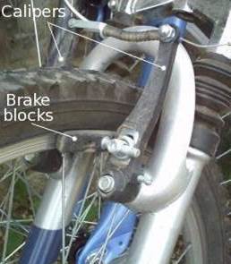
If you ride a bicycle, you know all about brakes. If you want to stop suddenly, you squeeze the brake levers on the handlebars. Thin metal cables running to the back and front wheels pull on small calipers, forcing thick rubber blocks to press against the wheels. As they do so, friction between the blocks and the metal wheel rims generates heat, reducing your kinetic energy, and bringing you safely to a stop.
Although most bicycles still use caliper brakes, some use disc or drum brakes instead (described below).
A closeup of bicycle brake blocks
Motorcycle
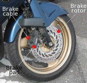
Motorcycles typically have disc brakes comprising a rotor and a brake pad. The rotor is a disc with holes (or slots) in it mounted on the side of the wheel. A brake pad, operated by a hydraulic cable, jams against the rotor to slow it down by friction. The holes in the rotor help to dissipate the heat generated.
Motorcycle brake rotor, brake block, and cable
Steam locomotive
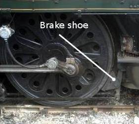
The brakes on a steam locomotive work the same way as a car's and are even more obvious. You can see the brake just behind the wheel in this photo. It clamps against the locomotive's driving wheels to slow them down. Since there are no tires on the wheels, the friction that stops the train comes from the immense weight of the locomotive pressing the metal wheels down onto the track.
A closeup of a steam engine wheel with the brake shoe
Airplane
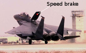
Airplanes have brakes inside their wheels to help bring them to a stop on the runway, but they can also use air brakes to increase drag (air resistance) and slow themselves down—a bit like parachutes. Jet fighters often have a speed brake, which is a large metal plate just behind the cockpit that can be hydraulically raised to increase drag and braking.
An F-15E Strike Eagle jet fighter airplane raises its aerodynamic speed brake to slow down as it comes into land.
Wind turbine
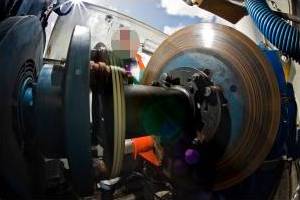
Wind turbines have brakes to stop their rotors (propellers) turning too quickly. The brake is mounted inside the nacelle (the square-shaped casing behind the propeller that contains the gearbox and generator). Most turbines have an anemometer on them to measure the wind-speed. If it rises above a safe level, the brakes come on automatically and bring the rotors to a standstill. It's a shame, because higher wind speeds mean more energy could be produced. But safety always comes first!
Wind turbine brake
A closer look at car brakes
Most cars have two or three different types of braking systems.
Disc brakes
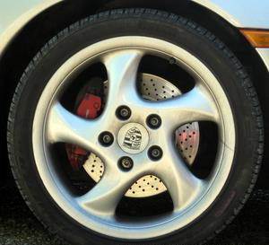
Peer through the hubcap of a car's front wheels and you can usually see a shiny metal disc just inside. This is called a disc brake. When the driver steps on the brake pedal, a pad of hard-wearing material clamps onto the brake disc and rubs it to make it slow down—in a similar way to bicycle brakes.
A closeup of a Porsche sports car front wheel showing the brake disk behind
Drum brakes
Some cars have disc brakes on all four wheels, but many have drum brakes on the back wheels, which work in a slightly different way. Instead of the disc and brake block, they have shoes inside the hollow wheel hub that press outwards. As the shoes push into the wheel, friction slows you down.
Simple animation showing how drum brakes work.
Handbrake
A car's handbrake applies the two rear brakes (disc or drum) in a slower, less forceful way through a lever that's typically located between the front seats. When you pull on the brake, a system of levers tugs on a pair of sturdy cables that apply the brakes to the back wheels. The handbrake system is completely mechanical and, unlike the conventional pedal brakes, doesn't use hydraulic fluid. That means it can be used (with very great care!) as an emergency braking system if the normal brakes fail.

Image result for brake system
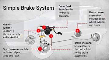
We all know that pushing down on the brake pedal slows a car to a stop. But how does this happen? How does your car transmit the force from your leg to its wheels? How does it multiply the force so that it is enough to stop something as big as a car?
The layout of a typical brake system
When you depress your brake pedal, your car transmits the force from your foot to its brakes through a fluid. Since the actual brakes require a much greater force than you could apply with your leg, your car must also multiply the force of your foot. It does this in two ways:
·         Mechanical advantage (leverage)
·         Hydraulic force multiplication
The brakes transmit the force to the tires using friction, and the tires transmit that force to the road using friction as well.
Before we begin our discussion on the components of the brake system, we'll cover these three principles:
·         Leverage
·         Hydraulics
·         Friction

Leverage and Hydraulics
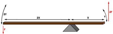
The pedal is designed in such a way that it can multiply the force from your leg several times before any force is even transmitted to the brake fluid.
In the fi­gure above, a force F is being applied to the left end of the lever. The left end of the lever is twice as long (2X) as the right end (X). Therefore, on the right end of the lever a force of 2F is available, but it acts through half of the distance (Y) that the left end moves (2Y). Changing the relative lengths of the left and right ends of the lever changes the multipliers.
The basic idea behind any hydraulic system is very simple: Force applied at one point is transmitted to another point using an incompressible fluid, almost always an oil of some sort. Most brake systems also multiply the force in the process.

Simple hydraulic system

In the figure above, two pistons (shown in red) are fit into two glass cylinders filled with oil (shown in light blue) and connected to one another with an oil-filled pipe. If you apply a downward force to one piston (the left one, in this drawing), then the force is transmitted to the second piston through the oil in the pipe. Since oil is incompressible, the efficiency is very good -- almost all of the applied force appears at the second piston. The great thing about hydraulic systems is that the pipe connecting the two cylinders can be any length and shape, allowing it to snake through all sorts of things separating the two pistons. The pipe can also fork, so that one master cylinder can drive more than one slave cylinder if desired.

Master cylinder with two slaves

The other neat thing about a hydraulic system is that it makes force multiplication (or division) fairly easy. In a hydraulic system, all you have to do is change the size of one piston and cylinder relative to the other.

Hydraulic multiplication

To determine the multiplication factor in the figure above, start by looking at the size of the pistons. Assume that the piston on the left is 2 inches (5.08 cm) in diameter (1-inch / 2.54 cm radius), while the piston on the right is 6 inches (15.24 cm) in diameter (3-inch / 7.62 cm radius). The area of the two pistons is Pi * r2. The area of the left piston is therefore 3.14, while the area of the piston on the right is 28.26. The piston on the right is nine times larger than the piston on the left. This means that any force applied to the left-hand piston will come out nine times greater on the right-hand piston. So, if you apply a 100-pound downward force to the left piston, a 900-pound upward force will appear on the right. The only catch is that you will have to depress the left piston 9 inches (22.86 cm) to raise the right piston 1 inch (2.54 cm).
Friction
Friction is a measure of how hard it is to slide one object over another. Take a look at the figure below. Both of the blocks are made from the same material, but one is heavier. I think we all know which one will be harder for the bulldozer to push.
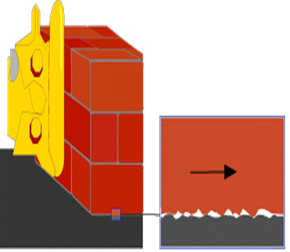
To understand why this is, let's take a close look at one of the blocks and the table:

Friction force versus weight

https://cdn.hswstatic.com/gif/brake-friction2.gif
Because friction exists at the microscopic level, the amount of force it takes to move a given block is proportional to that block's weight.
Even though the blocks look smooth to the naked eye, they are actually quite rough at the microscopic level. When you set the block down on the table, the little peaks and valleys get squished together, and some of them may actually weld together. The weight of the heavier block causes it to squish together more, so it is even harder to slide.
Different materials have different microscopic structures; for instance, it is harder to slide rubber against rubber than it is to slide steel against steel. The type of material determines the coefficient of friction, the ratio of the force required to slide the block to the block's weight. If the coefficient were 1.0 in our example, then it would take 100 pounds of force to slide the 100-pound (45 kg) block, or 400 pounds (180 kg) of force to slide the 400-pound block. If the coefficient were 0.1, then it would take 10 pounds of force to slide to the 100-pound block or 40 pounds of force to slide the 400-pound block.
So the amount of force it takes to move a given block is proportional to that block's weight. The more weight, the more force required. This concept applies for devices like brakes and clutches, where a pad is pressed against a spinning disc. The more force that presses on the pad, the greater the stopping force.

Powered by Blogger.